Fault analysis of 4-20mA transmitter with two-wire system
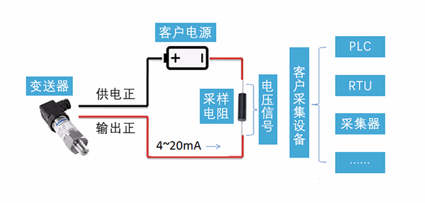
The following figure is a typical usage of most customer two-wire 4-20mA transmitters. After the transmitter is powered to work normally, the loop current is proportional to the pressure by collecting the pressure to be measured to output the 4 to 20 mA signal. The customer connects the sampling resistor(typical value 100 <UNK>, 250 <UNK>) on the return road, and the current flows through the sampling Resistor. After conversion to voltage signal, For use by the backend collection system. Typically, the sampled resistance is integrated into the collection device.
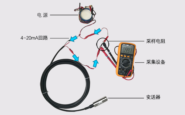
The following figure shows the actual application of the simulation diagram. The blue arrow refers to the current flow of 4 to 20 mA. The multimeter is used as a collection device. The sampling resistance is 250 euros, the zero current is 4 mA, and the collected voltage is about 0.997 V(0.004 mA × 250 euros = 1V).
/ Common Fault Analysis /
Common failure 1: the customer can not collect the pressure signal, or the collection value is obviously abnormal;
There are many reasons for this problem, such as customer collection equipment problems, wiring errors or product quality problems. To solve the problem, we must ensure that the transmitter works normally after being put on electricity.
A. Check wiring:
Check whether the wiring is correct, according to the label or instructions on the transmitter shell, the general red line of our product is the power supply, and the yellow line(blue line) is the output positive.
If the wire connection is found to be reversed, please do not worry about the damage of the transmitter. Conventional products are designed to prevent rewiring.
B. Measurement voltage:
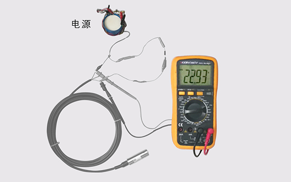
After the wiring is checked correctly, the multimeter is adjusted to the voltage file to measure the voltage value between the power supply and the output. The voltage value shall be within the power supply voltage of the transmitter. The power supply voltage of the transmitter can be viewed for product labels or instructions for use.
If the voltage value is not correct, check whether the customer equipment is normal.
C. Measurement of circuit current
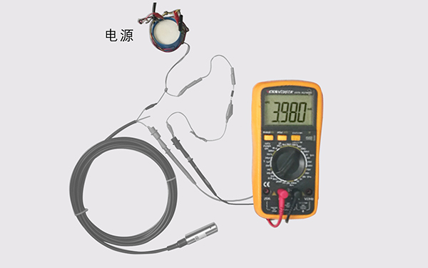
Disconnect the "output positive" line of the transmitter, adjust the multimeter to the current file and connect it into the current loop. Test the current value of the loop. The general non-pressurized state is about 4mA(the lower limit of the table pressure transmitter range is 0).
When doing the above test, pay attention to the setting of the current file and voltage file of the multimeter. You can refer to the setting of the two map multimeters above.
After the above three steps, the loop current value is still not about 4mA(0.5 accuracy, 3.92 ~ 4.08 mA) under the premise of ensuring that the multimeter used for testing is not free, then it can initially be determined as a product failure. After the sale department for further analysis.
Common failure 2: the transmitter test is not accurate, Super poor, pressure does not change;
(1) It is recommended to static the product in the air and check whether the power supply voltage is normal; Place the product in a vertical direction and test the accuracy of the loop current 4mA. For conventional 0.5 precision products, the zero current value should be between 3.92 and 4.08 mA.
(2) If the zero current of the product is normal, it is recommended that the customer check whether the equipment on the scene is normal, whether the cut-off valve is not opened, and whether the pressure pipe is blocked;
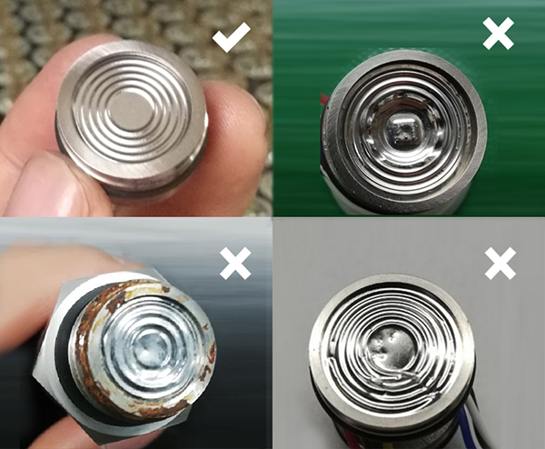
(3) to check whether the transporter sensor pressure diaphragm has any damage. If the diaphragm is damaged, it can only be returned to the factory for maintenance;
(4) The above can not solve the problem of customers, you can contact the company's after-sale department for further analysis.
|